Please refer to the Magnetic Effect of Electric Current Revision Notes given below. These revision notes have been designed as per the latest NCERT, CBSE and KVS books issued for the current academic year. Students will be able to understand the entire chapter in your class 10th Science book. We have provided chapter wise Notes for Class 10 Science as per the latest examination pattern.
Revision Notes Chapter 13 Magnetic Effect of Electric Current
Students of Class 10 Science will be able to revise the entire chapter and also learn all important concepts based on the topic wise notes given below. Our best teachers for Grade 10 have prepared these to help you get better marks in upcoming examinations. These revision notes cover all important topics given in this chapter.
Characteristics of Magnetic Field Lines
Construct a simple circuit with open ends M and N. Take a thick conducting wire of aluminium and connect it between the open ends. Now, place a magnetic compass near the aluminium wire and note the position of the compass needle. Now, close the switch to allow the current to flow through the wire and notice the deflection in the needle.
It can be concluded from this activity that electric current flowing through aluminium wire has produced a magnetic force that is exerted on the compass needle resulting in its deflection. Can we say that a magnetic field is related to an electric current?
Hans Christian Oersted (1777-1851) was the first scientist to observe that a compass needle gets deflected when placed near a current carrying conductor. By this, he concluded that electricity and magnetism are related to each other and called it electromagnetism.

Magnetic lines of force (magnetic force)
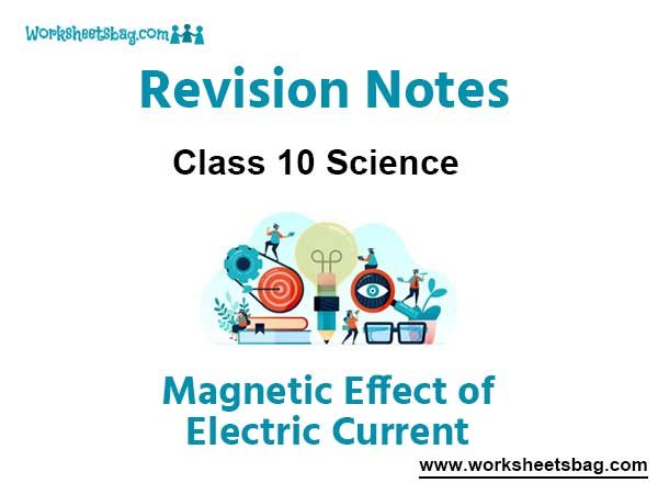
You know that a bar magnet can repel or attract another magnet depending on the nature of poles of the other two magnets that are facing each other. When a bar magnet is suspended by thread, its one end always points towards the geographic North Pole, called magnetic North Pole and the other end always points towards the geographic South Pole, called magnetic South Pole of the magnet.
Like poles repel and unlike poles attract each other.
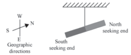
Take a drawing cardboard and sprinkle some iron filings on it. Notice the position of the iron filings as a whole. Now, take a bar magnet and slowly bring it below the cardboard.
You will observe that the iron filings tend to attract towards the magnet.
It is observed that most of the iron filings align themselves at poles. What does the pattern represent? It represents that the magnet exerts a force around its body with a stronger force near the two poles. A magnet produces a magnetic field, which can be detected by the force exerted on the iron filings. The regular pattern of the iron filings on the board represents the lines of magnetic field or lines of magnetic force called magnetic lines.
How to determine the shapes of magnetic field lines of a bar magnet?
Do you know the direction of a magnetic field inside the magnet?
Inside the magnet, magnetic field lines run from the South Pole to the North Pole where they emerge out. Therefore, we can say that magnetic field lines make closed curves.
- The region where magnetic field lines are crowded has relatively greater strength. Hence, in a magnet, strength of the regions near the poles is greater than other regions.
- It should be noted that a compass needle cannot point in two directions when placed at a point near the magnet. This means that no two magnetic field lines cross each other at a
point.
Characteristics of magnetic field lines
- Magnetic field lines emanate from the North Pole and terminate at the South Pole of a magnet. (Outside the magnet)
- The degree of closeness of magnetic field lines represents the relative strength of the magnet.
- No two field lines can intersect each other.
Non-uniform magnetic field due to stronger magnets

Magnetic field lines of the Earth
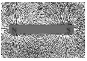
The Earth is treated as magnetic because it is assumed that a huge bar magnet is buried within its interior with the magnetic North Pole near the geographic South Pole, and the magnetic South Pole near the geographic North Pole respectively.
Since magnetic field lines originate from the magnetic North Pole and end at the magnetic South Pole, the Earth’s magnetic field lines originate from its geographic South Pole and end at its geographic North Pole respectively.
The magnetic poles of the Earth continuously change their position with time i.e., the magnetic North Pole becomes the magnetic South Pole and vice-versa. This phenomenon of flipping of poles is known as magnetic reversal. It is assumed by scientists that the Earth’s magnetic field has undergone 170 such reversals in the past 100 millions years.
We have learnt that when a magnetic compass is suspended freely, it aligns itself in geographic North-South direction. But in actual, the North pole of the magnetic needle is not exactly along the geographic North. This is depicted in the figure below.
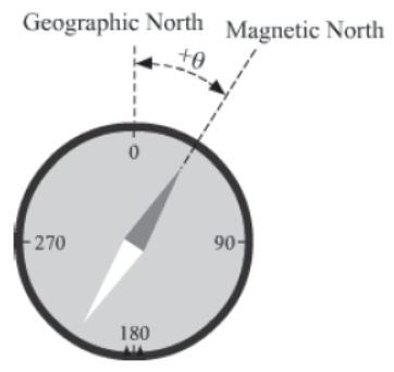
Thus, the angle of the horizontal plane between the geographic North (true North) and the magnetic North as shown in the above figure is known as magnetic declination. The magnetic declination varies with time and place.
- If magnetic North is towards East of true North, declination is taken positive.
- If magnetic North is towards West of true North, declination is taken negative.
Characteristics of a Magnetic Field Produced By Current Carrying Conductors
When a magnetic compass is brought near a current carrying wire, the compass needle gets deflected. Why does this happen?
The compass needle suffers deflection because a current carrying wire produces magnetic field lines around it.
Construct a simple open circuit with two open ends M and N respectively. Take a piece of aluminium wire and connect it with the two open ends. Now, bring a magnetic compass close to the aluminium wire and wait till the compass needle comes to rest. Now, allow the current to flow through the wire and notice the direction of deflection of the North pole of the compass needle with respect to the direction of the current flowing through the wire. Now, switch off the current and reverse the direction of the current by reversing the polarities of the battery. Now, switch on the current and observe the deflection of the North pole of the compass needle. You will find that the compass needle in this case gets deflected in the opposite direction. Why does this happen?
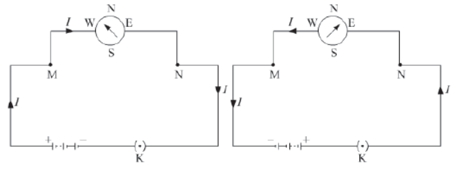
This happens because the direction of the magnetic field lines produced around a conductor depends on the direction of the current flowing through it. Hence, the direction of the magnetic field lines gets reversed when the direction of the current flowing through the conductor is reversed.
Pattern of magnetic field lines around a current carrying a straight conductor
Similar to bar magnets, a current carrying a straight conductor also has magnetic field lines around it. What factors are responsible for the pattern of magnetic field lines?
To understand the pattern of magnetic field lines around a current carrying a straight conductor, we will perform the following activity:
Using a rheostat box, a 12 V battery, and a key, construct a simple open electric circuit with open ends M and N respectively (you can obtain a rheostat box from your science laboratory). Now, take a cardboard sheet and insert an aluminium wire through the centre of the sheet. Connect the open ends of the wire with the open ends M and N of the circuit. Now, spread a few but equal iron filings over the sheet in such a way that the sheet stays horizontal. Now, turn the knob of the rheostat box to maximum to allow the current to pass through the circuit and the aluminium wire.
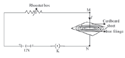
Now, turn the knob of the rheostat box slowly to lower the resistance and observe the movement of the iron filings. You will see that the iron filings arrange themselves in a regular pattern. Can you identify that regular pattern?
You will find that the iron filings align themselves in concentric circles around the conductor. What does this represent?
This represents that concentric magnetic fields are produced in the form of concentric circles around a current carrying the conductor.
How is the direction of concentric magnetic fields around the conductor related with the direction of current?
To understand this, slowly bring a magnetic compass near the aluminium wire and observe its deflection. Now, turn the knob of the rheostat slowly from its maximum value to its minimum value and simultaneously observe the direction of deflection of the North Pole of the compass needle. The compass needle deflects clockwise with an increased magnitude.
Now, switch off the current and reverse the polarities of the battery so that the direction of the current gets reversed. Keep the rheostat at its maximum value. Turn the key on and increase the current by turning the knob of the rheostat box towards its minimum value. You will find that as current increases, the deflection of the needle in an anti-clockwise direction also increases. Now, reduce the current slowly. What change in deflection of the needle do you observe? You can see that the deflection in the needle also decreases. Therefore, we can say that the strength of a magnetic field produced around a straight current carrying conductor is directly proportional to the magnitude of the current.
Similarly, if you move the compass away from the current carrying a wire, then you will notice that the deflection in the compass needle decreases and vice-versa.
Hence, from the above discussion, we find that the magnitude of the magnetic field produced by a straight current carrying a wire at a given point is
(i) directly proportional to the strength of the current passing through the wire
(ii) inversely proportional to the distance of this point from the wire
The direction of magnetic fields around a conductor is given by the right hand thumb rule.
Magnetic field due to a current carrying a circular loop
When a straight wire is bent, it becomes a circular loop. What happens when a current is allowed to pass through a circular loop? Will the circular magnetic fields produced around the current carrying a straight conductor also bend when the conductor is bent?
To understand the pattern of magnetic field lines around a current carrying a straight conductor, we will perform the following activity:
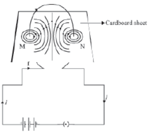
Take a rectangular cardboard sheet with two holes M and N respectively. Insert the two ends of a circular loop of the wire into the holes respectively. Now, connect both ends with a circuit (as shown in the following figure). Before closing the key, spread some iron filings over the sheet.
Hold the board gently and observe the pattern formed by the iron filings on it. You will find a regular pattern. Can you explain the origin of this regular pattern?
When a current is passed through a circular loop of wire, magnetic field lines are produced that pass through the loop in the direction normal to the loop area (given by Maxwell’s right hand rule). Every point on the current carrying wire produces its own concentric field lines with its centre at the point. The produced magnetic field lines are circular near the current carrying the loop. As we move away from the wire, concentric circles representing magnetic field lines become bigger, indicating that the strength of the produced magnetic force decreases gradually.
The magnitude of the field lines produced by a circular loop at its centre is
directly proportional to the amount of current
inversely proportional to the radius of the loop
Magnetic field due to a current carrying a solenoid
A solenoid is a long straight insulated wire, often wrapped around a cylinder-shaped body. A copper coil is wound around a cylindrical core, such that the core’s diameter is lesser than its length. It produces a magnetic field when electric current is passed through it. A strong magnetic field is produced inside a solenoid when a current is allowed to pass through it.
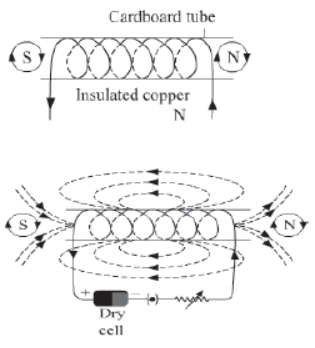
The given diagram shows the produced magnetic field lines when a current flows through a solenoid. The field lines are parallel inside (indicating that the magnetic field is uniform inside the solenoid) and curved outside the solenoid. This is similar to the magnetic field lines produced by a bar magnet. The direction of the magnetic field produced by the solenoid depends on the direction of the current flowing through it. Depending on the direction of the flow of current, one end of the solenoid acts like the North Pole of a magnet while the other end acts like the South Pole. In the figure given above, magnetic lines of force get emanated from the left end and terminate at the right end of the current carrying the solenoid. Hence, the right end of the solenoid acts as the North Pole while the left end acts as the South Pole.
Each turn of the coil behaves like a magnet when electric current is made to flow through it. In the above figure, the current is flowing in a clockwise direction; thus, the left hand side of each coil becomes the south pole, and conversely, the right hand side of each pole becomes the north pole. If we consider small coils as small bar magnets, with their opposite poles kept one after the other, then the entire coil behaves like a bar magnet.
If we take this analogy further (of taking one coil as one small bar magnet), then the more the number of small bar magnets combining to form a large bar magnet, the stronger will be the magnetic field of the complete bar. Hence, we can conclude that the more the number of coils in a solenoid, the stronger is the magnetic field produced by it.
When a solenoid is wound on soft iron, the magnetic field is very strong; but we cannot retain the magnetic property after the current is stopped. In such a situation, a solenoid is called an electromagnet. However, if we use a bar of steel instead soft iron, we can retain its magnetic properties even after the current is stopped. In other words, the bar of steel becomes a permanent magnet, but its magnetic strength is lesser than that of soft iron.
The strength of the magnetic field produced by a current carrying a solenoid
(i) is directly proportional to the number of turns in the solenoid
(ii) is directly proportional to the strength of the current in the solenoid
(iii) depends upon the nature of the core material
For example,the use of core materials such as soft iron increases the magnetic field.
Soft iron core is placed inside the transformer core to increase the magnetic field.
Construct a simple circuit using a solenoid. Place a magnetic compass near the solenoid and close the switch. The compass needle will deflect in a direction. Now, move the compass slowly near one end of the solenoid and observe the position of the needle. You will observe that the needle gets aligned horizontally along the length of the solenoid. Try to explain this with the help of Maxwell’s right hand rule. Now, bring the compass near the other end. You will find that the compass needle gets aligned horizontally in the opposite direction. Can you explain why the needle reverses its direction when moved from one end to the other of the current carrying the solenoid?
Games C. Maxwell (1831 – 1879) was one of the great physicists and mathematicians of the 19th century. He gave a unified model for electricity and magnetism called electromagnetism with his four sets of electromagnetic equations. He predicted the direction of the magnetic field produced around a current carrying a wire.
It is clear from the above activity that a current carrying the rod experiences a force when placed between two poles of strong magnets. The direction of displacement of the rod reverses when the direction of current is reversed. This suggests that the direction of force exerted on the rod is related with the direction of current.
Repeat the same process by reversing the direction of the magnetic field. You can easily observe that the rod will displace towards the right when the current flows from Q to P, and displaces towards the left when the current flows from P to Q. What does this suggest?
This suggests that the direction of force exerted on the rod is related with the direction of the magnetic field. Thus, we can say that the directions of current, magnetic field, and magnetic force are perpendicular to each other.
Experimentally, it is found that the magnitude of this force depends upon three factors:
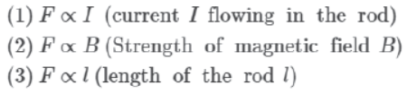


Apply Fleming’s left hand rule to find the direction of this magnetic force.
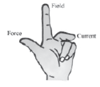
Fleming’s left hand rule
This rule states that if you stretch the thumb, index finger, and middle finger of your left hand such that they are mutually perpendicular to each other, then your index finger represents the direction of the field, the middle finger represents the direction of the current, and the thumb represents the direction of the force experienced by the conductor.
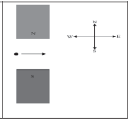
A charged particle is moving between two poles of magnets (as shown). Using Fleming’s left hand rule, find out the direction of the magnetic force exerted on the particle?
Do You Know:
Magnetic field is always produced by an electric current. The ions dissolved in blood move along the nerve cells. Thus, they produce a magnetic field, although a weak one. They produce sensations that we sense through the skin. This is because when we touch, the nerve cells transport an electric impulse to the specific part of our body that we have to use. A short lived magnetic field is produced there, which allows us to sense. Magnetic resonance imaging (MRI) is primarily a technique that uses magnetism, which is produced in our nerve cells to obtain computerised images of internal parts of our body such as the heart, brain etc.

Electric Motor
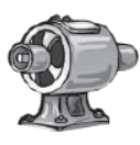
An electric motor is a rotating device that converts electrical energy into mechanical energy. A number of household devices such as fans, mixers, grinders, washing machines etc. consist of a motor.
Do you know how an electric motor works?
Motor principle
The basic principle on which the electric motor works is the magnetic effect of current. A current carrying a rectangular coil starts rotating when placed in a magnetic field. This happens because a continuous magnetic force acts upon it. Rotation of the coil also results in the rotation of the shaft attached to it. Thus, through this process, a motor converts electrical energy into mechanical energy.
Construction of an electric motor


The given figure illustrates the internal parts of a simple electric motor. A motor consists of a rectangular coil MNST of insulated copper wire. The coil is placed between two magnetic poles such that the magnetic field acts normal on lengths MN and ST.
The coil is connected with two carbon brushes at points A and B respectively. The inner sides of these carbon brushes are in contact with half rings C and D, which are insulated and in contact with an axle (not shown in the figure).
Functioning of an electric motor
When a current is allowed to flow through the coil MNST by closing the switch, the coil starts rotating anti-clockwise. Why does this happen? This happens because a downward force acts on length MN and at the same time, an upward force acts on length ST. As a result, the coil rotates anti-clockwise.
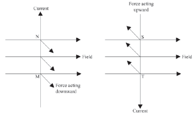
The current in length MN flows from M to N, and magnetic field acts from left to right normal to length MN. Hence, according to Fleming’s left hand rule, a downward force acts on length MN. Similarly, the current in length ST flows from S to T, and magnetic field acts from left to right normal to its length. Hence, an upward force acts on length ST. These two forces cause the coil MNST and the axle to rotate anti-clockwise.
After half-rotation, the position of length MN and ST get interchanged. Simultaneously, half ring D comes in contact with brush A and half ring C comes in contact with brush B respectively. Hence, the direction of current in coil MNST gets reversed and flows through TSNM.
An electric device that reverses the direction of current in a circuit is called a commutator
Thus, the split ring acts as a commutator of the electric motor. Now, due to the reverse direction of current in lengths MN and ST, an upward force acts on length MN, which pushes it up and a downward force acts on length ST, which pushes it down. As a result, the coil MNST further rotates anti-clockwise. The reversal of the current through the coil MNST repeats at each half-rotation, while its anti-clockwise rotation continues.
A commercial motor uses
- an electromagnet and permanent magnetic poles
- large number of turns in the rectangular coil
- A core of soft material such as iron on which the coil is wounded. The core becomes an electromagnet when a current flows through the coil. The coil–core system is known as the armature of motor.
Electromagnetic Induction
What would you expect if the same experiment is repeated with the South Pole of the magnet? Will the direction of deflection of the pointer be reversed?
From the above activity, we can conclude that the motion of the magnet sets up a current in the coil, whose direction depends on the nature of the incoming pole as well as on the direction of the motion of the magnet. What happens when the magnet is kept stationary and the solenoid is moved across it?
It is observed that a current is induced in the solenoid when it is moved across a stationary magnet. What does this indicate?
This indicates that a potential difference and current are induced in the solenoid, when either the solenoid or the magnet or both are moving.
The phenomenon of the generation of induced current in a conductor by changing the magnetic field or by moving a conductor in the magnetic field is known as electromagnetic induction.
The voltage generated in the circuit during electromagnetic induction is called electromotive force (e.m.f). Factors influencing induced e.m.f. are:
i) Number of turns of the coil,
ii) Rate of change of magnetic field linked with the coil.
This phenomena was first observed by Faraday. From his observations he enunciated two laws of electromagnetic induction.
First Law: A changing magnetic flux linking with a coil induces an electromotive force in the coil.
Second Law: The induced electromotive force is proportional to the rate of change of magnetic flux linked with the coil.

The direction of induced e.m.f is given by Lenz’s law according to which the direction of induced e.m.f. (or induced current) is such that it opposes the cause which produces it.
Michael Faraday (1791 – 1867) was one of the greatest physicists of the 19th century. Initially, he worked as a book binder in a book shop. He was so interested in experiments of science that he used to read the books that came for binding. He was the first to show that current is induced in a coil when a solenoid, magnet, or both are moved relative to each other. He also discovered the law of electrolysis.

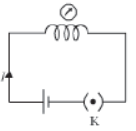
Take a long non-conducting cylindrical rod. Insert two coils of wires M and N on this rod. Ensure that the number of turns in coil M is greater than the turns in coil N. Now, connect a battery and a key to the ends of coil M and connect a galvanometer to the ends of coil N (as shown in the given figure). Allow the current to pass through coil M by closing the switch and observe the pointer of the galvanometer. You will see that the pointer comes back to zero after deflecting by a small amount. What does this indicate?
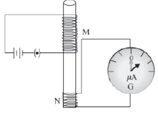
Deflection of the pointer of the galvanometer indicates that a temporary current is set up in coil N. Now, open the switch to stop the current in coil M. You will see that the pointer
again deflects, but in the opposite direction and comes back to zero. This indicates that a current has set up in coil N in the opposite direction.
From the above activity, we observed that as soon as the current in coil M reaches from zero to maximum or from maximum to zero, a current gets induced in coil N. Here, coil M is
called the primary coil, while coil N is called the secondary coil.
As a current is always associated with a magnetic field, the change in current in coil M causes a change in the associated magnetic field. This in turn changes the magnetic field
around coil N. The change in the magnetic field around coil N generates an induced electric current in the coil. This phenomenon is known as mutual induction.
The working of a transformer is based on the phenomenon of mutual induction.
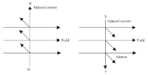
The direction of the current induced with respect to the directions of the magnetic field and motion of the coil is given by Fleming’s right hand rule.
Fleming’s right hand rule

The direction of current induced in a conductor can be obtained by holding the thumb, the index finger, and the middle finger of your right hand mutually perpendicular to each other.
In this situation, the thumb indicates the direction of the motion of the conductor, the index finger points along the magnetic field, and the middle finger points along the current induced in the conductor.

The phenomenon of electromagnetic induction is used in electric generators for the generation of electricity.
When current in a circuit flows only in one particular direction and does not change its magnitude, it is called Direct current or DC.
When current periodically changes its direction and magnitude about a mean value (called r.m.s. value), it is called Alternating current or AC.
Difference between A.C. and D.C.

Advantage of alternating current over direct current
If a direct current is generated at the power station, its voltage cannot be increased for transmission, and so due to passage of high current in the transmission lines, there will be a huge loss of electrical energy in the form of heat in transmission lines. However, we can increase or decrease the voltage of alternating current for transmission and thus it reduces heat loss in the transmission line.
Do you know that the current we receive in our houses is AC? Even the current produced in emergency generators and in hydroelectric power houses is alternating current. The alternating current that we use in our homes has a frequency of 50 Hz. It means that the current changes its direction 50 times in a second. The supply of AC voltage is controlled by a transformer.
Electric Generator
An electric generator is a machine that generates electricity by rotating its rotor in a magnetic field. Thus, it converts mechanical energy into electrical energy.
Principle
The basic principle on which electric generator works is electromagnetic induction. When rotor rotates in a magnetic field, current is induced in the rotor.
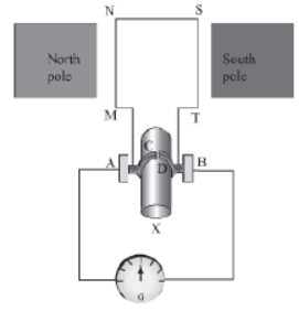
Construction
A generator consists of a rectangular coil MNST of insulated copper wire placed between two strong magnetic poles.The two ends of the coil MNST are connected with brushes A and B of rings C and D respectively. The inner sides of the rings are insulated. They are attached with an axle X, which can be rotated mechanically. Brushes A and B are connected with a galvanometer that can measure the flow of current in coil MNST.

Working
When the axle is rotated, lengths MN and ST move up and down respectively. Since lengths MN and ST are moving in a magnetic field, a current gets induced in these lengths caused by an electromagnetic induction. The direction of the induced current in both the lengths is given by Fleming’s right hand rule.
Since length MN is moving upwards in the magnetic field that acts from left to right, the direction of the induced current will be from M to N. Similarly, the direction of the induced current in length ST will be from S to T. Hence, an induced current will set up in the coil in the direction MNST, which produces deflection in the galvanometer.
After half-rotation, length MN starts moving down, whereas length ST starts moving up. The direction of the induced current in the coil gets reversed i.e., the induced current will now flow from T to M via S and N i.e., TSNM. Therefore, we can conclude that after each half-rotation, the direction of the induced current is reversed. This current is called an alternating current (AC). An AC reverses its direction after equal time intervals. A machine with this arrangement is called an AC generator.
To get a current that flows in one direction only, a split ring is used.
In this arrangement, brush A always remains in contact with the length moving up, whereas brush B always remains in contact with the length moving down. Here, split rings C and D act as a commutator. In this case, the direction of the current induced in the coil will be from M to T via N and S for the first half-rotation, and from T to M via S and N for the second half-rotation of coil MNST. Hence, we get a unidirectional current called direct current (DC). A machine with such an arrangement is called a DC generator.
Do You Know:
Electricity supplied to our homes, school buildings, company buildings etc. is AC, which reverses its direction after every second with a frequency of 50 Hz. Most power stations in the world generate AC than DC. This is because AC can be transmitted over very long distances without much loss of energy.
Domestic Electric Circuit
Vikram has read in his science book that electricity reaches our homes, schools, factories etc. through thick aluminum and copper wires. The supply voltage is 220 V. He has scrutinized some electrical appliances such as bulbs, heaters, and refrigerators in his house and found that they all operate at 220 V. He wonders how these appliances run simultaneously with only 220 V supply voltage.
Vikram’s confusion can be sorted out by understanding the concept of domestic electrical circuits.
Domestic wiring
Electricity is transferred to our homes through a pair of insulated copper or aluminum wires. This pair consists of a red color wire (called live wire, L), and a black color wire (called neutral wire, N). In addition to these wires, a green color wire known as the Earth wire, E is also connected with the circuit. In India, 220 V potential is supplied through live wire, while neutral wire has ground potential of zero volts.
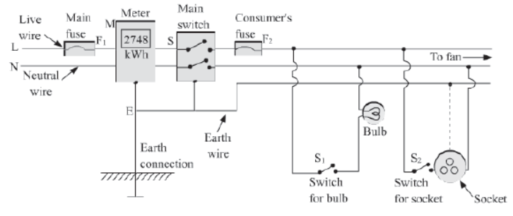
In the above diagram, the pair of wires L and N first enter the main box, which is placed outside the house. From here, live wire L goes into the main fuse F1 having a high rating of about 50 A. Then, both wires enter the electricity meter that records the electricity consumed in units, where 1 unit = 1 kWh = 3.6 × 10⁶ J. The wires then go to the main switch, S. Electricity supplied to the house can be cut off using this switch.
The extensive use of electricity is due to the convenience and usefulness associated with this form of energy. Domestic uses of electricity include lighting, heating, cooling and nowadays, even cooking. The electricity supply board usually provides alternating current at 220 V.
Alternating current consists of three phases or what we see as wires of three different colours.
1. Red wire is the live wire
2. Black wire is the neutral wire
3. Green wire is the earth wire

Here, the red and the black wires are called the supply wires, while the green wire is for safety.
Why use the earth wire?
Earth wire is quite necessary in a household appliance. It causes a leaking current to flow harmlessly to the ground, thereby preventing the user of the appliance from getting an electric shock.
Importance of Earthing
We can receive an electric shock on touching a running appliance. This is caused by the leakage of current from the appliance. Earthing provides a safety measure against the electric shock, caused by the leakage of current. A third wire called the Earth wire (E) is also used in domestic wiring. This wire has green insulation over it. A copper plate connected to the main switch via the meter is connected at one end of this wire, E.

Sometimes, the insulation of a live wire burns due to excessive heating. A naked live wire may lead to an electrical shock. To protect the appliance against an electrical shock, its metallic case is connected with the Earth wire. Hence, a domestic socket is composed of three wires, namely the live wire, neutral wire, and Earth wire.
Open and Closed circuits
When the two ends of an electrical circuit are not connected, no current flows through the circuit. We say that the circuit is not complete and call it an open circuit. No current flows
through the circuit in this situation.
On the other hand, when the two ends of an electrical circuit are connected and the circuit forms a closed loop, we call it a closed circuit.
Every circuit in ‘switched-off’ condition is an open circuit.
Switches: It is a device which is connected in the live wire so as to turn ‘ON’ or ‘OFF’ the current in the circuit.
Types of switches:
1) Single pole switch: A single pole switch is a simple switch which is used with an appliance to start or stop the flow of current in it. This switch only disconnects the live wire from the appliance.
2) Double pole switch: A double pole switch is a main switch in the distribution board, used to switch on or off the main supply. This switch disconnects both live and neutral wires simultaneously. We often use such switches in a staircase etc.
Why switch should always be connected in the live wire?
- If the switch, connected to live wire which is at high potential, is turned off, then the switch cuts the path of current to the appliances connected to the live wire. This is because, in this case, both the live and neutral wires connected to the ends of the appliances come at zero potential and hence does not allow current to flow in the circuit. Thus, if required, we can safely carry out repairs for our appliances as appliances in these case also are at zero potential.
- But if the switch, connected to a neutral wire which remains at zero potential, is turned off, then also current will not flow through the appliances in this case as the circuit is not closed. But the live wire (or appliances) still remains at high potential in this case. So, it would becomes dangerous to carry out repairs in appliances as current would flow from the appliances to the person’s body (body being at low potential).
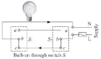
Working of dual control switch/ double pole switch
Two dual control switches S1 and S2 are connected at the top and bottom of the staircase, respectively. Now, the bulb connected to both the switches can be put on or off using any of the two switches.
Situation (a): In this situation, bulb does not glow as live wire connecting the point c of switch S1 (in ‘OFF’ position) through point b and c of switch S2 (in ‘ON’ position) is not making a complete circuit.

Situation (b): In this situation, switch S1 is pressed ‘ON’ and switch S2 is in same position (i.e. in ‘ON’ position). The live wire, which provides the current to point c of S1 from point b and c of switch S2 , now gets connected to point b of switch S1. Hence, the circuit is complete and thus the current flows through the bulb and the bulb glows.
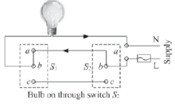
Situation (c): In this situation, switch S1 (in ‘OFF’ position) will disconnect the path of the current from point c to b of switch S1 but joins the point a to b of S1 creating a new path for the current. Simultaneously, switch S2 (in ‘OFF’ position) will disconnect point c from b and connect point b with a of switch S2. Again the current flow from S2 to S1 through point b to a of S2 to a to b of S1. Hence, the bulb glows.
Series and Parallel circuits
Depending upon how the appliances are connected to each other, domestic electrical circuit can be of two types—parallel circuit and series circuit.
When the appliances are connected end-to-end one after another, the circuit is called series circuit.
When the appliances are connected parallel to each other between two points, the circuit is called parallel circuit.
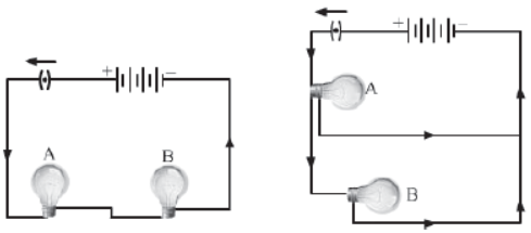
In domestic circuit, parallel circuit is always preferred over series circuit.
Electric fuse
An electric fuse is a safety device that protects the wiring against excessive heating caused by an excess supply of current. It melts when heavy current flows through the circuit, thereby causing the circuit to become open.
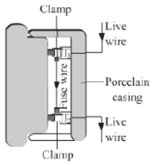
Characteristic of electric fuse
- Fuse wire has low melting point. It is generally made up of an alloy of lead and tin.
- Fuse wire is always connected in the series with the live wire. Its resistance is higher than that of the copper wires. So it gets heated up much faster than the copper wire when excessive current flows through it.
- Current rating of the fuse wire decides its thickness. More the current rating of the fuse wire, more will be its thickness.
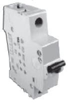
Miniature circuit breaker (MCB)
An MCB is a device which functions as a fuse, but does not require replacement. MCB falls down to break the circuit when heavy amount of current flows through it. Once the fault is rectified, the MCB is reset.
Excessive flow of current can be caused by any of the following two cases:
I. Short circuiting
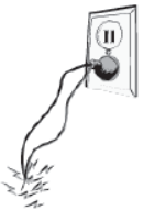
Short circuiting occurs when naked live and neutral wires touch each other. In such a case, the resistance of the circuit becomes very less. Now, according to Ohm’s law, current is inversely proportional to resistance. Thus, the lowering of resistance of the circuit raises the current to a significant amount. As a result, the wires become hot and a spark is caused by Joule’s heating effect of current. This situation is known as short circuiting.
II. Overloading
A large amount of current is withdrawn from the circuit, when a large number of electrical appliances of high power-rating are switched on at the same time or connected in a single multi-plug. This situation is called overloading. It may even lead to a fire in the circuit.
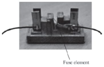
To prevent any damage by short circuiting or over loading, an electric fuse (that consists of a low melting point wire) is used. The wiring of the circuit is made of low resistance copper wire of a certain thickness. This allows only a maximum amount of current to flow through it, which is called its safe limit.
If an amount of current flowing through a circuit exceeds its safe limit either caused by short circuiting or over loading, the excess heat caused by Joule’s heating melts the wire. This results in the breaking of the circuit, thereby preventing the appliances from damage.
Depending on the thickness, fuse elements are rated as 1 A, 2 A, 3 A, 5 A, 10 A, 15 A, and so on. For example, a 10 A fuse element melts and breaks if the current exceeds its limit of 10 A.
Short circuiting and overloading are the major hazards related to electricity. There are various other hazards of electricity against which we should be cautious and should take precautions.
Precautions to be taken while using electricity:
- Never touch switches with wet hands.
- Ensure all electrical appliances are properly earthed.
- Ensure MCB, fuse and switch are connected to live wire.
- Never repair an appliance while in use.
- The wiring used must be properly insulated.